Ursnif malware is an information stealing/banking Trojan that has been around since 2016 and continues to evolve. Its capabilities include stealing of:
- System information
- List of installed applications
- List of installed drivers
- List of running processes
- List of network devices
- External IP address
- Email credentials (IMAP, POP3, SMTP)
- Cookies
- Certificates
- Screen video captures (.AVI)
- Financial information via webinjects
Recently, a new variant of Ursnif malware emerged, targeting Italian users via a spam email campaign.
the Cyberbit Malware Research team investigated this new variant and discovered that it has a lot of encryption, obfuscation and compressions techniques. Some are well known, some are custom made for this new variant. These techniques can be used to hide from anti-virus products – as they hide the real payload and its malicious API calls/strings.
We determined that this sample also performs process hollowing using direct system calls – a technique we covered thoroughly in our last article. The direct system calls injection can be used to bypass user mode hooks in cases when the patch guard mechanism is present and SSDT hooks can’t be placed.
This article will focus on reverse engineering of the encryption, obfuscation and compression techniques in this sample. SHA256 of the sample analyzed here is 81798ea125359ca4e618a5619cd856f95f3fb809f5f3022a42563bd3b627f2ca
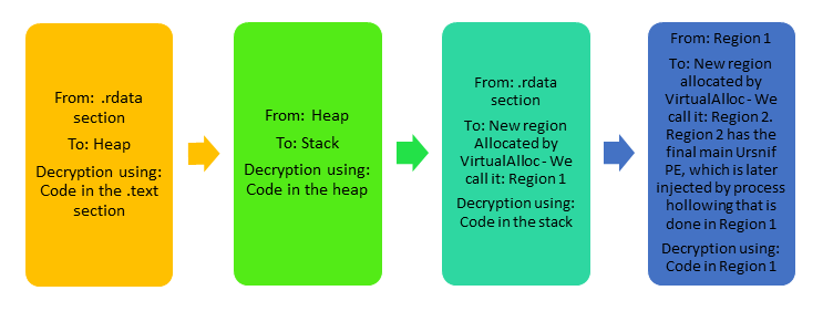
The decryption phases are summed up in this table and the flow chart. Detailed descriptions follow below.
| Phase | Encrypted code/data location | Destination of decrypted data | Decrypted data content | Decryption algorithms used | Decryption algorithms location |
| 1 | .rdata section of main module | Heap | Decryption algorithm no.2 and the algorithms at phase 2 (encrypted) | Decryption algorithm no.1 | .text section of main module |
| 2 | Heap | Stack | Deobfuscation (Byte-Swapping) algorithm and decryption algorithm no.3 | Decryption algorithm no.2 | Heap |
| 3 | .rdata section of main module | New allocation by VirtualAlloc (Region 1) | Ursnif main PE compressed with Lighty Compressor and XORed with 0x7B, Code for process hollowing with direct system calls | Deobfuscation (Byte-Swapping) algorithm and decryption algorithm no.3 | Stack |
| 4 | Region 1 | New allocation by VirtualAlloc (Region 2) | Ursnif main PE | Lighty Compressor Decompression Algorithm and a XOR with 0x7B | Region 1 |
Ursnif Malware Decryption Phases
The NX (Non-Executable) bit
The PE file structure contains a header called Optional header. In this header, there is a field called DllCharacteristics. One of the values of this field is IMAGE_DLLCHARACTERISTICS_ NX_COMPAT (0x0100), also known as the NX-bit.
If this value is set, the processor will not execute any code that resides in specific memory areas. This is done in order to prevent code being executed from a forbidden memory area, for example; The heap and the stack.
If the NX-bit is not set, code can be executed from these memory areas and buffer overflow attacks will be easier to implement on the targeted process.
The new variant of Ursnif was compiled with the NX-bit not set. We will see how it utilizes it to execute code from both the Heap and the Stack of its process.
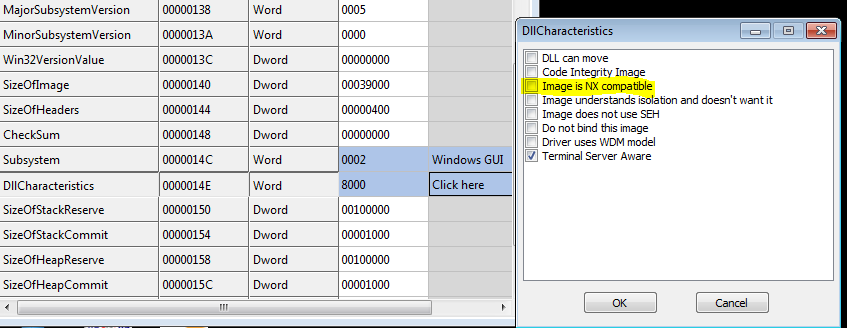
Figure 1 – A screenshot from CFF explorer shows that the NX-bit of Ursnif executable is not set
First layer of ursnif malware encryption
Ursnif begins its first unpacking stage with a decryption function located at 0x406110. The encrypted code resides at the .rdata section of the main module of the process at address 0x429AA0 and its size is 1910 (0x776) bytes.
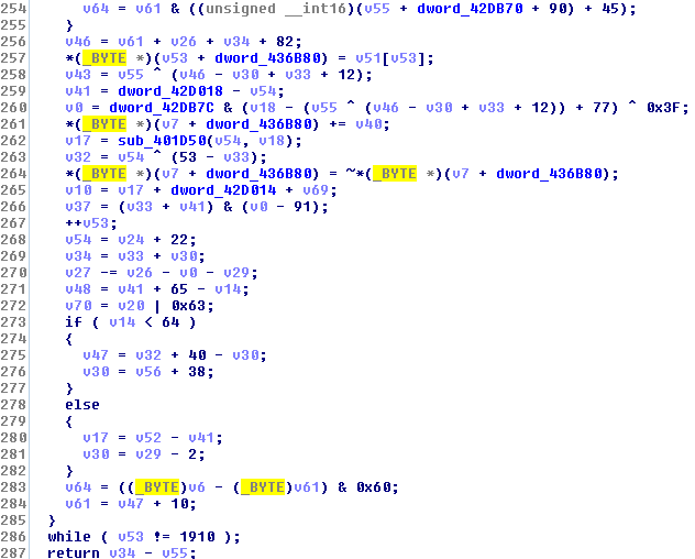
Figure 2 – Part of the first decryption function. In line 286 you can see it is looping through all 1910 bytes of the encrypted code
Because the NX-bit of the image is off, code can be executed from the heap, even though it has Read-Write protection. The decrypted code is placed on the heap. This what the code looks like before and after decryption:
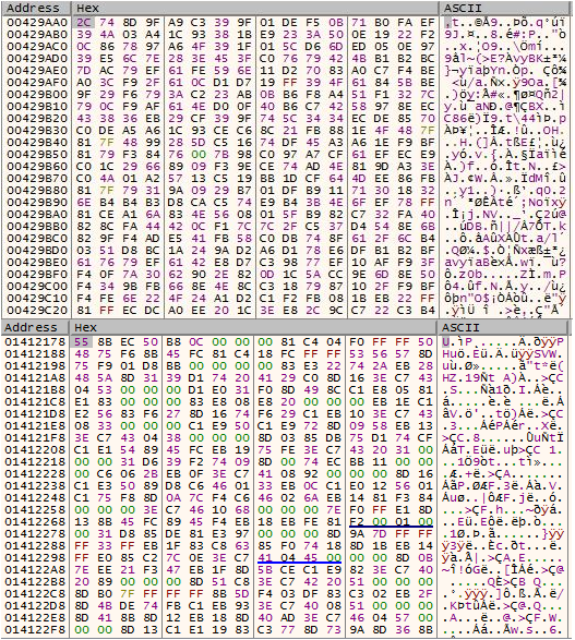
Figure 3 – The code before decryption (above) and after decryption. The decrypted code is placed on the heap
The decryption function is huge but after reverse engineering, the decryption algorithm is only a few lines. Most of the instructions do not directly/indirectly affect the decryption. It can be written as the following pseudo code (This sample is a 32-bit image):
for (i = 0; i < 1910; i++):
x = (i + 0x7F) * (0xFFFFFF82) * (i + 1)
y = sign_extend(enc[i]) + x
z = lowest_byte(y)
t = sign_extend(z)
dec[i] = lowest_byte(not(t))
Definitions:
enc, dec – The pointer to the encrypted/decrypted buffer.
enc[i], dec[i] – the byte located at the encrypted/decrypted buffer at location i.
lowest_byte – the lowest byte (least significant byte) of the 32-bit DWORD.
sign_extend – equivalent to the movsx assembly instruction.
Explanation for sign_extend:
if z = 0x4E (01001110 in binary), the sign of z is its most significant bit – 0. It means that z is a positive number, so the rest of the bits of t will be filled with the sign of the byte (0), hence t = 0x0000004E.
If z = 0xAE (10101110), the sign of z is its most significant bit – 1. It means that z is a negative number, so the rest of the bits of t will be filled with the sign of the byte (1), hence t = 0xFFFFFFAE (because 0xF = 1111 in binary)
not – equivalent to the not assembly instruction – flipping all the bits (from 0 to 1 or vice versa)
Note – the sign_extend function does not affect the result of the decryption because we look only on the least significant byte. It is noted here for the sake of accuracy.
Second layer of encryption
The code that was unpacked to the heap has two parts. The first part decrypts the 2nd part from the heap to the stack. The stack is another memory area from which code should not be executed, but since the NX-bit is off, the processor will execute it. You can see in figure 4 that part of the code on the heap isn’t actually code that makes sense – This is the 2nd part which is encrypted. Its size is 958 (0x3BE) bytes and has a rather simple decryption algorithm:
for (i = 0; i < 958; i++):
dec[i] = lowest_byte(enc[i] – 0x11B599c)
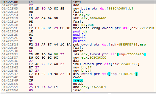
Figure 4 – Part of the decrypted code on the heap which is encrypted by itself
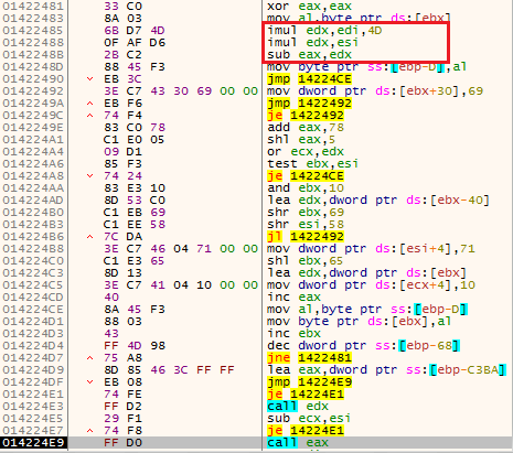
Figure 5 – The instructions inside the red rectangle performs the decryption. The last instruction on this figure (call eax), executes the decrypted code
Third layer of encryption
The decrypted code on the stack looks for the address of kernel32.dll on the PEB, and then for the address of GetProcAddress from this module. Using GetProcAddress it fetches the VirtualAlloc address. You can see the characters ‘G’, ‘P’, and ‘A’ on the stack in figure 6. They are accustomed to looking for the address of GetProcAddress. Using VirtualAlloc it allocates a buffer of 74280 (0x12228) bytes. The buffer is filled with an encrypted code that lies in the .rdata section of the malware’s process at address 0x417873.
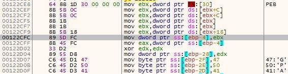
Figure 6 – Fetching the address of the PEB. The letters ‘G’, ‘P’, and ‘A’ are later used to fetch the address of kernel32.GetProcAddress
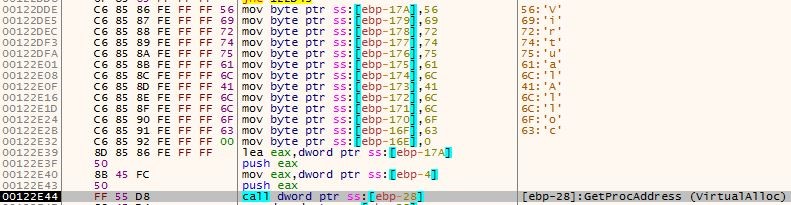
Figure 7 – VirtualAlloc letters on the stack and a call to GetProcAddress(VirtualAlloc)
The code in the buffer is both obfuscated and encrypted. It first goes through deobfuscation using this byte-swapping algorithm:
x = 0x12227 * 0x5B + 0x15
for (i = 74279; i >= 0; i–):
y = x
remainder = y % 0x12228
temp = buf[remainder]
x = x – 0x5B
buf[remainder] = buf[i]
buf[i] = temp
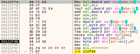
Figure 8 – The byte-swapping (deobfuscation) algorithm
After the deobfusction, the buffer goes through this decryption algorithm:
for (i = 0; i < 74280; i++):
x = (i + 1) XOR 0xBC XOR ( (i + 1) * 0xBC )
y = lowest_byte(enc[i] – x)
dec[i] = lowest_byte(y – ((i + 1) XOR 0xF5))
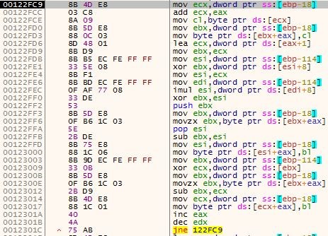
Figure 9 – The decryption routine
After this decryption, the code in the buffer is executed.
Last layer – Compressed Ursnif PE & Process Hollowing Using System Calls
The code in the buffer continues the unpacking process. It allocates a new buffer of 41984 (0xA400) bytes. It decompresses to this buffer the Ursnif PE (XORed with 0x7B) that lies within itself. The Ursnif PE is compressed using a compressor called “Lighty Compressor” and its decompression algorithm can be seen in figure 10. When the decompression finishes, the new buffer is XORed with 0x7B and finally we have in memory the last PE of Ursnif, with its .bss section.
You can read more about the “Lighty Compressor” here. For your convenience, I have copied here .asm file from the previous link for direct download. This .asm file decompresses a Lighty-Compressed file. You just need to fill in the input file, output file name and the output file size (this is the size allocated by VirtualAlloc in the last example). Compile it with FASM.
This final PE is injected using process hollowing via direct system calls, with the original file as the hollowed process. The malware functionality continues in the hollowed process.
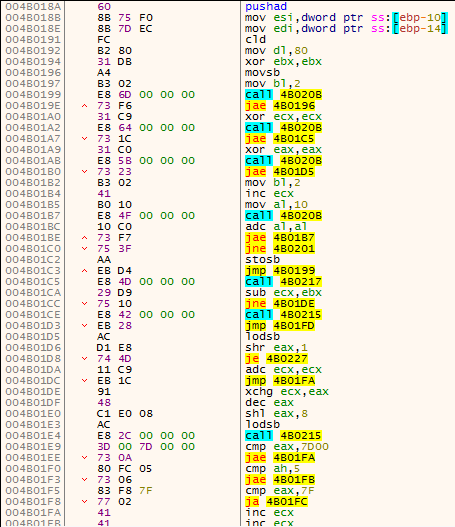
Figure 10 – Part of the Lighty Compressor decompression algorithm
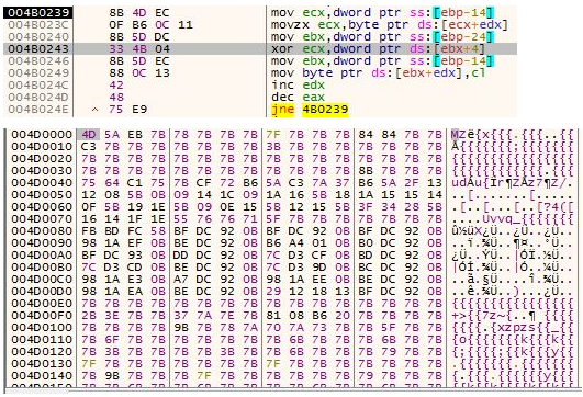
Figure 11 – In the upper box, you can see the XORing of the decompressed PE file. In the lower box you can see how the buffer looks after XORing, the first two bytes were XORed and are now MZ – the PE magic
As most modern malware do and as we talked about in our previous article, this variant rears its head with the infamous direct system calls injection method. It reads a copy of ntdll.dll from the disk in order to copy the system call numbers, creates a suspended process of itself and injects the final unpacked main Ursnif PE into it by direct system calls. It does it in a way very similar to Trickbot and it also uses CRC32 for hashing Windows API functions’ names.
Hod Gavriel is a Malware Analyst at Cyberbit.
Watch FREE webcast to learn How to Prevent the Next Financial Cyberattack with Next-Gen Technology